• Home
  • Blog
  • How Do Electric Chain Hoists Work

How Do Electric Chain Hoists Work

Wondering how do electric chain hoists work? Learn the difference between wire rope and chain hoists, plus core components, working principle and common industrial configurations.
Introduction

Electric hoists are the most widely used light-duty lifting devices in industrial settings, and they fall into two primary categories: wire rope electric hoists and electric chain hoists. Wire rope hoists offer higher load capacity and greater lifting height, making them ideal for heavy-duty, long-travel material handling. Electric chain hoists, by contrast, feature a more compact design and simpler maintenance, and are extremely popular for small-to-medium capacity lifting, assembly work and routine material transfer.

Table of Contents

1. Core Components of an Electric Chain Hoist

An electric wire rope hoist is a motor-driven lifting device that realizes the vertical lifting, lowering and horizontal traversing of heavy materials. Its core configuration includes a drive motor, reduction gearbox, reliable braking system, rope winding drum and high-strength steel wire rope. Controlled by handheld pendant switches or wireless remote controllers, this equipment effectively reduces manual labor intensity, avoids safety risks caused by manual lifting, and adapts to long-term, repeated heavy-load operation in industrial environments. Compared with chain hoists, wire rope hoists feature stronger load capacity, smoother operation and wider application coverage in industrial heavy lifting scenarios.
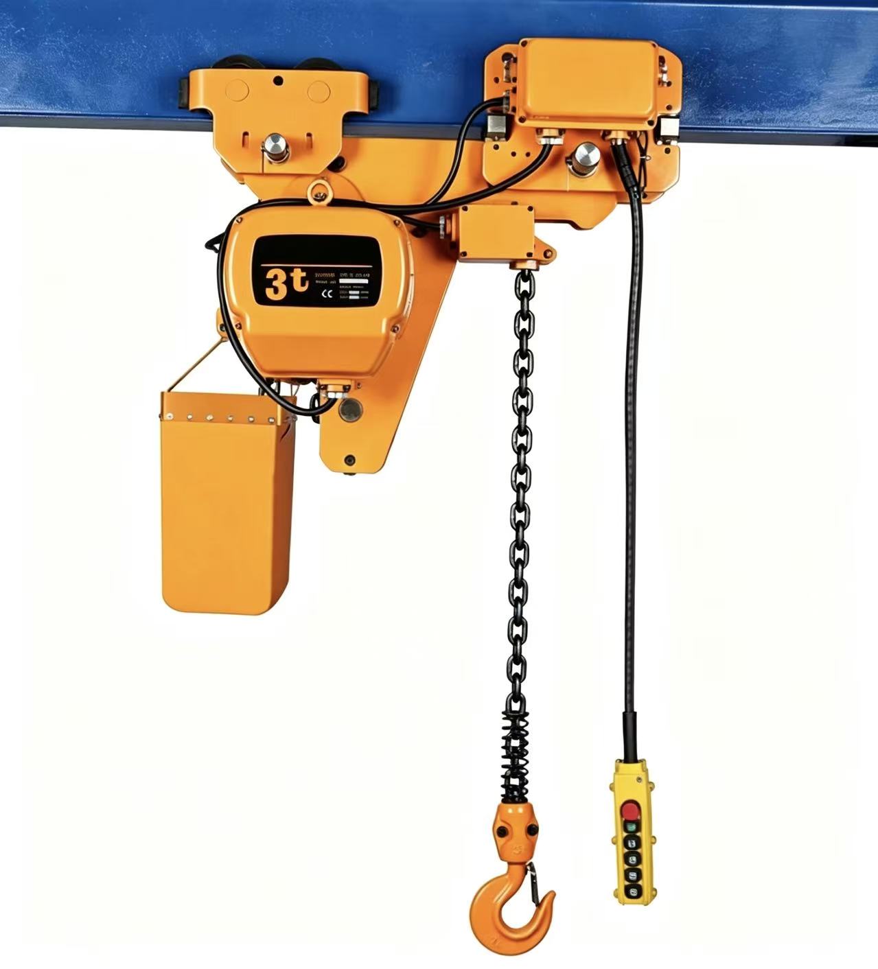
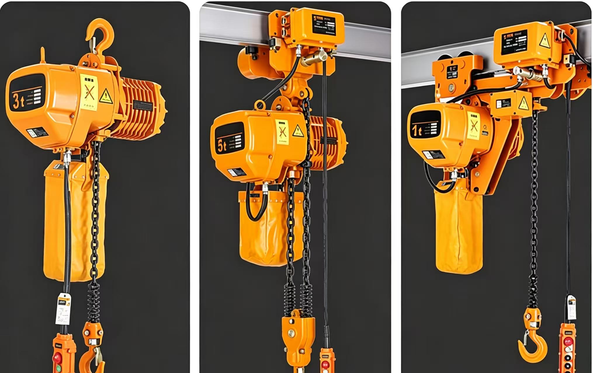
Every electric chain hoist relies on an integrated set of parts to deliver smooth, safe lifting performance. The core assemblies include:
  1. Lifting Motor

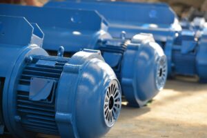
    The primary power source of the unit. Most industrial models use high-torque conical rotor motors, engineered for frequent direct starting under intermittent duty cycles. Both single-speed and two-speed motor options are available to match different operational requirements.

  2. Gear Reduction Box


    A multi-stage gear transmission system that reduces the motor’s high rotational speed and amplifies output torque, delivering the slow, high-force rotation required for heavy load lifting.

  3. Electromagnetic Brake


    The core safety component, featuring a normally closed, spring-loaded design. It locks the drive shaft by default and releases only when energized, preventing load drop during operation or in the event of unexpected power loss.

  4. Load Sprocket


    The drive wheel that meshes with the load chain. As it rotates, it pulls the chain to raise or lower the hook assembly, serving the same function as the drum on a wire rope hoist.

  5. Alloy Steel Load Chain


    Typically made of Grade 80 heat-treated alloy steel for high strength and excellent wear resistance. It is the main load-bearing component connecting the sprocket to the hook assembly.

  6. Chain Guide


    A critical guiding component that keeps the chain properly aligned during winding and unwinding, preventing chain jumping, jamming and uneven wear.

  7. Hook Assembly


    A forged steel hook fitted with a safety latch, mounted on a thrust bearing for free rotation. Higher capacity models use multi-pulley hook blocks to distribute load weight evenly.

  8. Travel Trolley (optional)


    A motorized or manual trolley that mounts the hoist to an overhead beam for horizontal load movement. This assembly is not included on stationary fixed-mount models.

2. Step-by-Step Working Process

When operated via push-button pendant or wireless remote, the full lifting cycle follows a clear, sequential flow.
  1. Operation Signal Activated


    When the operator presses the “UP” or “DOWN” button, the control circuit closes and supplies power to both the lifting motor and the brake assembly.

  2. Brake Releases and Motor Starts


    The electromagnetic brake energizes first, overcoming internal spring pressure to release the drive shaft. The lifting motor then starts rotating and sends rotational force into the gear reducer.

  3. Speed Reduction and Torque Amplification


    Inside the gearbox, multi-stage gears reduce the motor’s high-speed rotation and significantly multiply torque. This converts fast, low-force motor output into slow, high-force power capable of lifting full-rated loads.

  4. Sprocket Drives the Load Chain


    The gearbox output shaft turns the load sprocket. Sprocket teeth mesh with the load chain, pulling it smoothly through the chain guide. The hook assembly at the end of the chain rises to lift the load, or descends to lower it into position.

  5. Automatic Braking on Stop or Power Loss


    When the operator releases the control button, or if power is cut unexpectedly, both the motor and brake lose power instantly. Internal springs re-engage the brake discs and lock the drive shaft firmly. The suspended load stays held securely in place with zero slippage.

3. The Chain Guide: Function & Working Principle

The chain guide is a small but indispensable component, with a direct impact on chain service life and overall operational safety.

Key Functions

First, it maintains proper chain alignment. It guides the load chain neatly onto and off the sprocket, preventing chain jumping — a common fault where the chain slips out of the sprocket teeth. A faulty chain guide can lead to jamming, twisting and uneven wear, causing premature chain failure and elevated safety risks.
Second, it supports automatic height limiting. As the chain guide moves with the winding pattern, it actuates the limit switch mechanism at preset upper and lower heights, cutting power to stop the hoist automatically. This prevents over-lifting, hook collision and chain damage.
 

How It Works

The chain guide itself does not rotate with the sprocket. As the sprocket turns to wind or unwind the chain, the chain guide travels horizontally along the sprocket axis, staying aligned with the active chain link at all times. It feeds the chain into the sprocket teeth at the correct angle and guides it out through a precision-sized gap, ensuring every link seats properly.

When the chain guide reaches either end of its travel range, it pushes against the limit rod mounted on the hoist housing, triggering the limit switch to shut off the lifting circuit. This provides reliable automatic end-stop protection for both lifting and lowering operations.

4. Common Configurations of Electric Chain Hoists

Industrial electric chain hoists come in standardized configurations to suit different on-site working conditions.

By Motor Speed

  • Single-speed hoists: Equipped with a fixed lifting speed, ideal for general material handling and high-volume routine lifting tasks.
  • Two-speed hoists: Feature a standard working speed and a slow precision speed (common ratios of 10:6 or 6:1), designed for delicate assembly, mold handling and applications requiring accurate load positioning.

By Mounting Type

  • Stationary fixed-mount hoists: Mounted to a fixed anchor point, used for dedicated lifting stations where horizontal movement is not required.
  • Trolley-mounted hoists: Paired with a motorized travel trolley to run along overhead I-beams or crane girders, supporting full-workshop material transport. Standard travel speed is 20 m/min, with 30 m/min available as an option.
  • Low-headroom hoists: Compact, shortened designs built for facilities with limited overhead vertical space, maximizing usable lifting height.

Electrical Control System

All configurations include a complete electrical package: a control box, push-button pendant station, limit switches and interconnecting wiring. Pendant control voltage is typically 36V or 380V, with relay-based switching inside the control box to manage lifting, lowering and travel movements.

Final Thoughts

At its core, an electric chain hoist converts electrical power into controlled lifting force through a motor-gearbox-sprocket power path, with a fail-safe electromagnetic brake as its primary safety feature. The chain guide plays a quiet but critical role in protecting the load chain and enforcing travel limits.
Understanding how these components work together helps operators use equipment correctly, identify early signs of wear, and carry out routine maintenance that extends service life and keeps workplace operations safe and efficient.
Comments
Great things in business are never done by one person. They’re done by a team of people. We have that dynamic group of peoples
Scroll to Top

Get the quote

Fill out the form below, and we will be in touch shortly.